Here is a small side project that I have been working on as part of my larger Hexapod project. For my Hexapod I am using Hitec HS-485 servos which have their axis supported by a bearing. So radial loads are well supported and there is very little thrust load to worry about. However there is some torsional load required to support the weight of the body and to keep the legs rigid. Many higher end servos counter this by providing an idle bearing on the opposite side, there are also various brackets available which provide this idle bearing to lower range servos. But why spend $5 on a bracket when you have a 3D printer?
3D Printed Bearings:
I had a look around at other peoples solutions to this, lots of them either did not worry about the extra support or they just used a small bolt to make a hinge. I saw this as being somewhat unnecessary resistance and thought I would try and find a nice light bearing to work into my design. Unfortunately any bearings that you can buy tend to come in standard sized and are way over rated (all I need is a couple Hz oscillation and load in the realm of a couple hundred grams). This also has the unfortunate consequence that they are unnecessarily heavy.
So I picked up a couple thousand 1/8″ bearing balls from ebay and got to work designing some nice light bearings that can be customized to meet a very specific purpose; satisfying space requirements and minimizing weight.
They are printed in three parts;
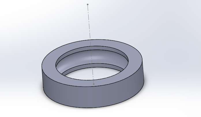
There is an outer ring with a semicircle cut revolved around the inner diameter. The diameter of the bearing balls are 1/8″ or 3.175mm. I found a cut diameter of 3.22mm to work very nice. This allows for a tiny bit of expansion/contraction and error in the print whilst still allowing nice smooth and rigid movement;
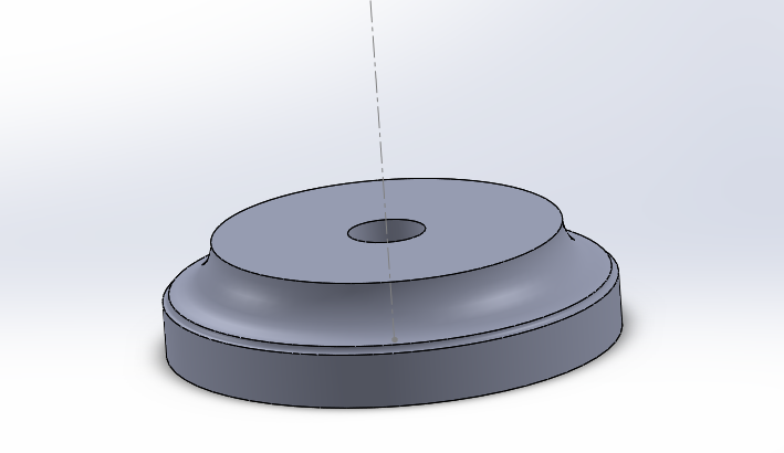
There is a upper inside piece which has a quarter circle of the same radius (3.22mm) cut out. I make the radius of these inner pieces about 1mm smaller in diameter than the outer piece. In the examples here I have the inner pieces 14mm diameter and the outer pieces 15.2mm in diameter. There is also an M2 hole through the centre;
Finally there is a lower inside piece. This is the piece that I customize to suit a mount. In the example here is is identical to upper piece only with an M2 nut trap in the bottom to allow a M2 bolt to tighten the upper and lower piece together and hold he bearing together. The upper surfaces of the inner pieces are inherently rough and lock together due to the nature of FDM, so this bolt can just be tightened down and it is unlikely to come loose. I however like to put a drop of locktight in the nut before I tighten down – just to make sure.
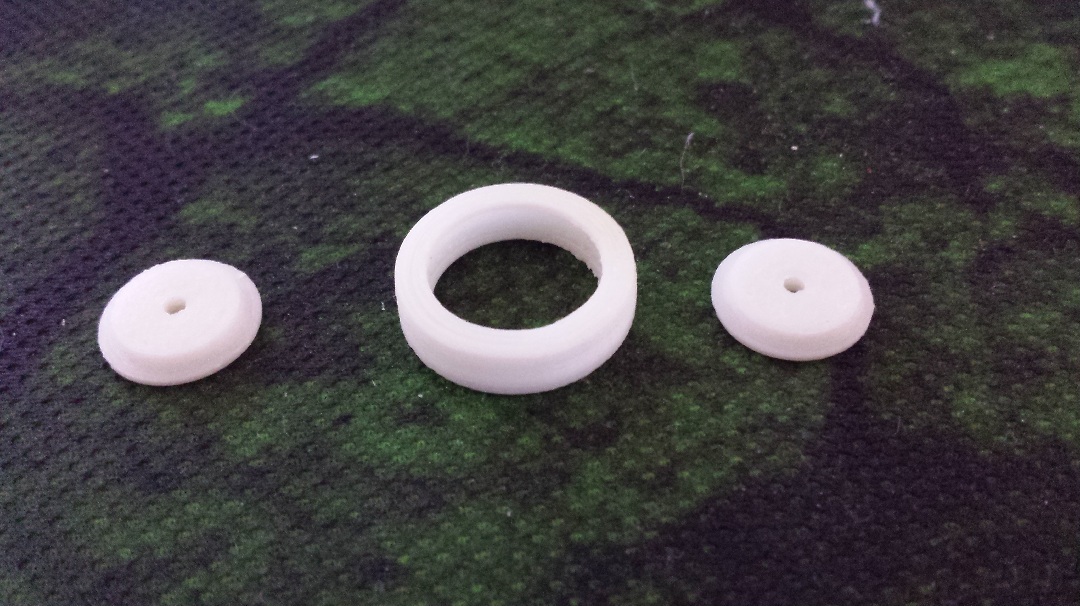 All three printed parts
Here are the test piece STL’s if you would like to download them and tinker with them.
Download:
 BearingTop.STL
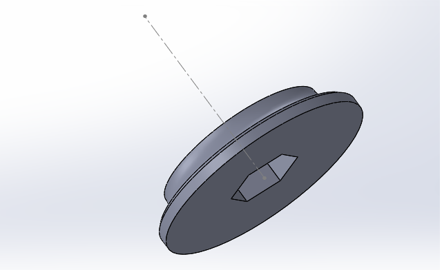
Download:
Download: